Tag Archives: RPi


JeegVa44 ErgoZero Split Mechanical Keyboard

JeegVa44 ErgoZero Split Mechanical Keyboard

License: GPLv3

tags: Raspberry Pi RaspberryPi Raspberry Pi Pico RaspberryPiPico MicroPython

Status: COMPLETED.

A split hand-wired custom Mechanical Keyboard based on the Waveshare RP2040-Zero.

My second keyboard designed from scratch, this time split.

Components

  • 2x RP2040 (KMK on Waveshare RP2040-Zero), USB-C port
  • 44x switches
  • 2x TRRS breakout boards
  • 1x TRRS cable
  • 28x M2 5mm screws
  • 14x M2 10mm stand-offs
  • 4x M4 Low profile brass heat inserts
  • 4x M4 6~8mm Socket cap head screws
  • 8x 10mm Rubber feet
  • 46u Round hole female pin header
  • 3D printed case, plate, feet

Story

I wanted a portable split keyboard with a gentle vertical stagger, sixth column available and four thumb keys.
I also wanted to learn more about proper CAD design, so this time I ditched Blender and I designed everything from scratch in Onshape.

Keymap (dev)

Keymap

Repository

https://github.com/slabua/keyboards/tree/main/jeegva44ergozero

3D Model

3D model of JeegVa44 ErgoZero rev1 also available on:
Onshape: [Link]
Thingiverse: https://www.thingiverse.com/thing:5866262
Printables: https://www.printables.com/model/404303-jeegva44-ergozero-rev1

Some photographs and renders


AtreuSLB50+ Mechanical Keyboard

AtreuSLB50+ Mechanical Keyboard

License: GPLv3

tags: Raspberry Pi RaspberryPi Raspberry Pi Pico RaspberryPiPico MicroPython

Status: COMPLETED.

A hand-wired custom Mechanical Keyboard based on the Raspberry Pi Pico.

Finally I had the time to wrap up my little side project started about three months ago, and I thought to share it here. Although inspired by the Atreus, I couldn't quite find the right compromise among the non-split ergo keyboards, so I decided to make my own.

Components

  • 1x RP2040 (KMK on Raspberry Pi Pico), USB-C port
  • 50x switches
  • 1x SSD1306 128x64px 0.96in IIC OLED display
  • 2x EC11 rotary encoders
  • 1x EVQWGD001 rotary encoder
  • 1x Pimoroni IIC trackball breakout
  • 1x Active buzzer
  • 2x micro switches (bootsel, reset)
  • 3D printed case (5-10° tilt), plate, pcb

Story

The design started from a semi-automated customised process by forking an OpenSCAD hotswap pcb generator repository, subsequently heavily worked on Blender. I had also added cutouts for per-key rgb, but in the end I gave up the idea of hand wiring the LEDs. At least in this version which, for me, has been an insightful experience.
I am slowly finalising the firmware configuration and I will eventually put it on github as usual. Wiring diagram and key layout will come along later.

Keymap

[Coming Soon]

Repository

https://github.com/slabua/keyboards/tree/main/atreuslb50+

3D Model

3D model of AtreuSLB50+ rev1 also available on:
Thingiverse: https://www.thingiverse.com/thing:5458679
Printables: https://www.printables.com/model/262446-atreuslb50-rev1

Some photographs


Pico Motorcycle Dashboard

Pico Motorcycle Dashboard

tags: Raspberry Pi RaspberryPi Raspberry Pi Pico RaspberryPiPico MicroPython

Status: Currently under development.
https://github.com/slabua/PicoMotorcycleDashboard

A Motorcycle Dashboard based on the Raspberry Pi Pico and the Pimoroni Pico Display Pack.

Components

  • Raspberry Pi Pico
    • Main control board
  • Pico Display Pack
    • Input:
    • Button A
    • Button B
    • Button X
    • Button Y
    • Output:
    • 240x135 px IPS display
    • RGB LED
  • Sensors
    • Built-in temperature sensor
    • (internal ADC on pin 4)
    • DS18B20 Temperature sensor
    • (currently up to 3 in parallel)
  • Work in progress
    • Connection for Battery/Fuel/Rpm readings

Wiring Diagram

Breadboard - Full diagram

Breadboard

Breadboard - Display directly mounted on the back of the Pico (not shown)

Breadboard


Usage

Screens

Home

Home

  • A: Go to next (Battery) screen
    • If pressed again within 3 seconds,
      cycle through all the screens
  • B: Cycle Brightness presets
  • X: Select Multiple or Single Temperature mode
  • Y: If Multiple (*) or Single (**) Temperature mode:
    • Cycle Temperature sources (**)
    • Cycle bars style (*) (globally)
  • X+B: Cycle Colour palette
  • Y+B: Show Info scroll banner (hold)

Battery

Battery

  • A: Go to Home screen
  • B: Cycle Brightness presets
  • X: Continuous / Discrete battery representation
  • Y: Cycle Graphics style
  • Y+B: Show Info scroll banner (hold)

Fuel

Fuel

  • A: Go to Home screen
  • B: Cycle Brightness presets
  • X: -
  • Y: Cycle Bars style (globally)
  • Y+B: Show Info scroll banner (hold)

Temperature

Temperature

  • A: Go to Home screen
  • B: Cycle Brightness presets
  • X: Cycle Temperature sources
  • Y: Clear history for the current temperature source
  • Y+B: Show Info scroll banner (hold)

RPM

RPM

  • A: Go to Home screen
  • B: Cycle Brightness presets
  • X: Cycle Ramp style
  • Y: Cycle Bars style (globally)
  • Y+B: Show Info scroll banner (hold)

Stats

Stats

  • A: Go to Home screen
  • B: Cycle Brightness presets
  • X: Update Configuration file
  • Y: Reset uptime
  • X+B: Reset Configuration file
  • Y+B: Show Info scroll banner (hold)

A Practical Introduction to the Raspberry Pi Pico

A Practical Introduction to the Raspberry Pi Pico

tags: Raspberry Pi RaspberryPi Raspberry Pi Pico RaspberryPiPico MicroPython

Introduction

My name is Salvatore and I am a Development Engineer at 株式会社Rist.

  • Robotics team, responsible for Robotics R&D.
  • Robot design, control, motion, perception and manipulation.
  • Image analysis, recognition and classification.
  • AI algorithms design and implementation.
  • UI/UX design and implementation.

About this article

This article aims to give a quick introduction to the Raspberry Pi Pico, through simple step-by-step instructions to its setup and providing some code examples in MicroPython.

※ No soldering nor external components are required to follow this tutorial~

What is the Raspberry Pi Pico

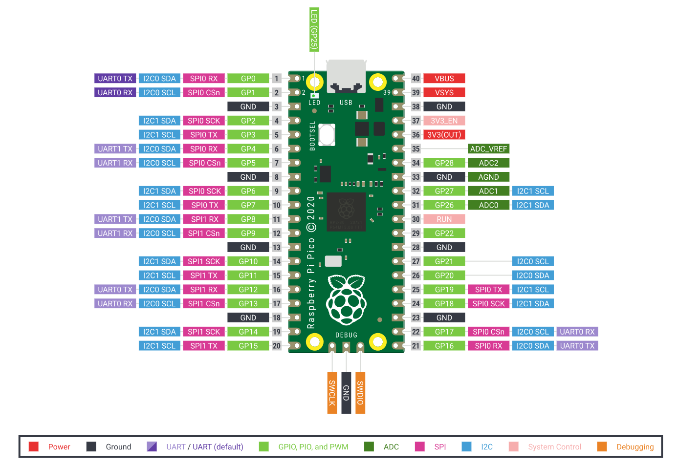
The Raspberry Pi Pico is a microcontroller able to acquire various inputs and provide outputs through a series of GPIO pins, similar to a Raspberry Pi computer [1][2].
Microcontrollers are most suitable for embedded applications or any other situations in which the use of a full computer running an Operating System would be considered not necessary.

Environment Setup

~

User group

In order to have read/write permission to the serial port created upon connecting the Pico, the current user must belong to the dialout group.
Verify the current groups the user belongs to with:

$ groups

If the user does not belong to the dialout group, add it as follows:

# usermod -a -G dialout $USER

To make the changes effective, relog the current user to the system.

※ A reboot might be needed after performing the operation, in the case which a simple relog would not be sufficient.

Thonny and MicroPython

Proceed with the installation of the Thonny Python IDE [3]:
As of writing this article, the easiest way to get the most updated version of the IDE on a variety of linux distributions is through pip.

$ pip install thonny

※ For more information and other platforms support, visit thonny.org.

Once installed, the Thonny IDE would look similar to:

In order to control the Pico, it is necessary to switch the Python interpreter to MicroPython (Raspberry Pi Pico).

Click on the bottom right corner to switch the interpreter:
Python 3.7.9 > Configure interpreter...
Then select MicroPython (Raspberry Pi Pico) from the combo box list.

Or alternatively, from the Thonny menu, select:
Run > Select interpreter... > Interpreter > MicroPython (Raspberry Pi Pico)

Connecting the Pico to the PC

As the Pico comes out of the box, it needs to be initialised by installing the MicroPython firmware.
This can be done easily from the Thonny IDE itself.

To connect the Pico to the computer:

  1. Press and hold the BOOTSEL button on the Pico
  2. Connect the Pico to the computer via micro USB
  3. Release the BOOTSEL button

The Pico is now connected as a USB mass storage device.

MicroPython firmware installation

By clicking the Stop/Restart button on the Thonny toolbar, the IDE will connect to the Pico and it will prompt for the MicroPython firmware installation.

Proceed with the installation.

At this point, the environment setup is complete.

Code

As mentioned in the introduction, for this tutorial no external component are required.
The provided sample code will make use of the on-board power LED (GPIO 25) and the embedded temperature sensor.

LED test

Let's skip the basic LED on/off/blink tests and try the PWM controlled brightness test instead.

Create a new file and paste the following code [1]:

from machine import Pin, PWM
from time import sleep

pwm = PWM(Pin(25))
pwm.freq(1000)

while True:
    for duty in range(1024, 65025, 2):
        pwm.duty_u16(duty)
        sleep(0.0001)
    for duty in range(65025, 1024, -4):
        pwm.duty_u16(duty)
        sleep(0.0005)

By running this code, the on-board LED will pulse smoothly according to the values specified in the ranges of the duty cycles and the sleep intervals.

※ The value 65025 corresponds to the LED maximum brightness.

Temperature test

For the temperature test, use the following code [4]:

import machine
from time import sleep

sensor_temp = machine.ADC(4)
conversion_factor = 3.3 / 65535

while True:
    reading = sensor_temp.read_u16() * conversion_factor
    temperature = 27 - (reading-0.706)/0.001721
    print(temperature)
    sleep(2)

The temperature measured by the sensor will be printed in the Shell standard output every 2 seconds.

Putting it together

The following code will make the on-board LED pulse with variable speed.

from machine import Pin, PWM
from time import sleep

sensor_temp = machine.ADC(4)
conversion_factor = 3.3 / 65535

pwm = machine.PWM(machine.Pin(25))
pwm.freq(1000)

while True:
    reading = sensor_temp.read_u16() * conversion_factor

    temperature = 27 - (reading-0.706)/0.001721
    print(temperature)

    if temperature < 19:  # Lower threshold
        steps = 16
    elif temperature > 23:  # Higher threshold
        steps = 64
    else:
        steps = temperature

    for duty in range(0, 65025, int(steps**2)):
        pwm.duty_u16(duty)
        sleep(0.001)
    for duty in range(65025, 0, -int(steps**3)):
        pwm.duty_u16(duty)
        sleep(0.05)

The LED will blink in three different ways, depending on the ambient temperature measured by the on-board sensor:

  • Temperature below the lower threshold:
    • The LED pulses at a slow pace
  • Temperature within the thresholds interval:
    • The LED pulses at a pace proportional to the temperature
  • Temperature above the upper threshold:
    • The LED pulses at a fast pace

Adjust the Lower and Higher thresholds to best suit the local environment temperature.

Stand-alone operation

It is time to store the program in the Pico.

File > Save as...
And select Raspberry Pi Pico from the following dialog window:

In order to make the code run upon power up, the file must be named main.py.

※ Safe operating voltages are between 1.8V and 5.5V.

Alternatives

Recently, various boards are taking advantage of the RP2040 chip to provide custom solutions. One of them is the Seeed Studio XIAO RP2040, currently available through a Free Shipping campain in 221 countries and counting.
More on this and other tiny boards soon! Please check it out if you like.

References

[G] https://github.com/slabua/RaspberryPiPico
[Q] https://qiita.com/slabua/items/ed0a49cd587d0c8103b8
[1] https://www.raspberrypi.org/documentation/pico/getting-started/
[2] https://projects.raspberrypi.org/en/projects/getting-started-with-the-pico
[3] https://hsmag.cc/picobook
[4] https://tkrel.com/14899


Raspberry Pi – Webcam streaming

Now it's time to make my old Creative Live! Cam Vista IM (VF0260) Webcam work on the RasPi, I also tried a new Logitech C270 HD Webcam and they both work flawlessly out of the box.
I have tried three softwares for the webcam, which I previously tested on my desktop machine running Fedora and I wanted to try them also on the Pi. These are:

  • fswebcam
  • motion
  • mjpeg-streamer

Let's now have a look at them.
(more…)


Raspberry Pi – Firmware and Updates

Now that the system is installed on the SD card and the ssh service has been configured properly, we're going to take care of the system and firmware updates; few words have to be said about the system partitioning scheme.
The Raspbian installation consist of two partitions: the fat16 boot partition, that contains the firmware needed to the Pi to boot, and the ext4 system partition.
(more…)


Raspberry Pi – SSH and static IP

By the time I received my RasPi, I didn't have an usb keyboard yet, so my first concern was about how to use it without the keyboard from the very first boot. It wasn't clear whether the ssh daemon would be active by default or not, and I've also got to know that for some distributions, or even among different updates of the same distribution, its default state changed over time.
I found out that in Raspbian, ssh is installed by default but it's not configured to start up automatically since the first boot.
(more…)


Raspberry Pi – Preparing the SD card

Download the image:

First step would of course be that to choose and install a linux distribution on the SD card.
I'm personally a RedHat/Fedora user since quite some time but I thought, for the RasPi, to give Debian a go. I decided to install Raspbian “wheezy”, an optimised version of Debian for the Raspberry Pi, and it comes with LXDE as default desktop environment, for those who care about it.
You can download the image from the RaspberryPi Downloads page.
(more…)


Raspberry Pi has arrived

It's been almost one month since I received my Raspberry Pi. I actually received two of them, both on day 18th of July, one from Farnell/Element14 via Royal Mail and the other one from RS Components via DHL, which I got for my friend Giuseppe. So far so good, the little RasPi is behaving very well, and I'm testing its stability keeping it up and running, checking cpu and memory usage.
I installed the system on a Sony 8GB SDHC Class 4 card, which I got along with my Sony HX9V camera, bought in Hong Kong a couple of years ago. I'm surprised by the speed of this sd card, achieving 17.4MB/s in read speed and 11.8MB/s in write speed, checked on the RasPi itself with a dd test.
As PSU I'm using my HTC Legend phone charger, rated 5V/1A, which is flawlessly powering it up, by now, for one good week already.
I plan to write some posts as I go developing stuff with it, hopefully and time permitting, so if you are interested, stay tuned : )